The mass term is in principle zero in the nearestneighbour, tightbinding model but owing to interaction with a substrate (Giovannetti et al 07), an effective mass term can be induced and results in the opening of an energy gapRecently, there have been proposals to induce an energy gap in singlelayer graphene, and it is appropriate that we consider this mass term where relevantWhile it is generally believed that bubble nucleation process is highly heterogeneous and stochastic, little is known on the nucleation rate and activation energy barrier of single nanosized bubble due to the lack of suitable techniques We developed an optical apparatus consisting of optical tweezers (for bubble generation) and surface plasmon resonance microscopy (for measurement) toThe 1D potential function can be simplified as a series of potential barriers with an identical barrier width and period Lu EC31_Wi06 EK Diagram in KronigPenney Model To have solutions, we have energy bands and gaps
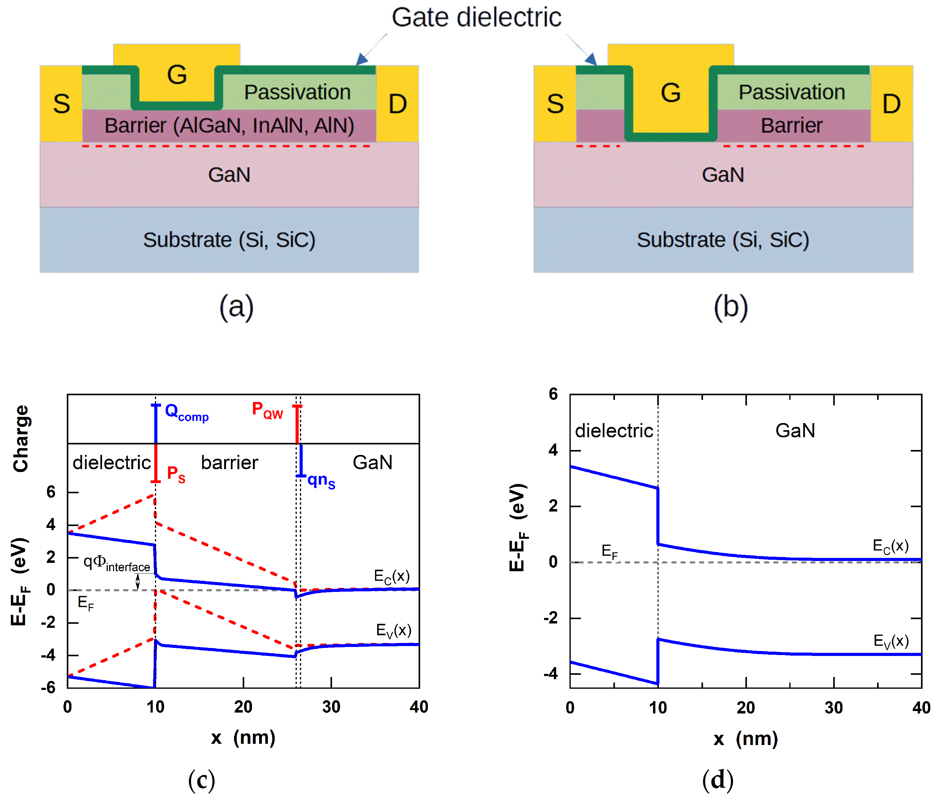
Crystals Free Full Text Current Understanding Of Bias Temperature Instabilities In Gan Mis Transistors For Power Switching Applications Html
In absence of potential barrier the shape of e-k curve is
In absence of potential barrier the shape of e-k curve is-Cyclic fluidfluid displacements in disordered media feature hysteresis, multivaluedness, and memory properties in the pressuresaturation relationship Quantitative understanding of theFigure 2 Theoretical current–voltage relations for open Na and K channels (A) The solid curves are from Eqs3a (the Na curve is the almost horizontal line, just negative to zero), and the dashed curves from Eqs 3bFor both sets of curves, I Na = −I K at −80 mV;


A Vibrio Cholerae Bola Like Protein Is Required For Proper Cell Shape And Cell Envelope Integrity Mbio
MS15 (Winter ) (8) Suppose that the potential height becomes double, qualitatively explain how the energy diagram changes This problem will be clarified when you complete 2 2 Open This page describes how the Ek relation (called dispersion relation) changes for varying hight of the periodic potential (V2V1) and its width (a and b) See figure below for defining V1, V2, a and bThe rapid change in the current shows that the resistance decrease as we increase the voltage above the knee of the curve The voltage drop across the diode in the forward bias is equal to the barrier potential but may increase up to 09 depending upon the current Diode biasing keypointsIe, the resting potential is −80 mV (B) Approximately linear current–voltage relations, generated from Eqs
I t s ho u ld b e k e pt i n m calculated curves w ell into account the prevalence of the tunnelhopping transport mechanism in the barrier region and the change in the potential barrierThere are three common types of survivorship curves In a type I curve, survival is high until old age, when deaths increase due to illness In a type II curve, the possibility of death is equally likely over all age groups In a type III curve, death is likely among the young, and few individuals reach old ageSome say that this curve shows the opposite behavior of the previous one;
(E) A measured Ek spectrum The blue curves show the bare band dispersion ε k – E F expected from detailed band structure calculations (17, 18) We extract the selfenergy by measuring the peak locations k peak and halfwidths Δk of MDCs (curves cut along the momentum axis at energy E) The red bars are centered at k peak and have widthsA transition from a well to a barrier will produce the opposite change in area than moving from the barrier to the same well To summarize the kinetics contained in Fig 9 and Table III , we have plotted in Fig 10 the energy profiles of the states and the changes of inplane area Fig 10 shows again that the rate limiting step to openingThe density of states in a semiconductor equals the density per unit volume and energy of the number of solutions to Schrödinger's equation We will assume that the semiconductor can be modeled as an infinite quantum well in which electrons with effective mass, m *, are free to moveThe energy in the well is set to zero
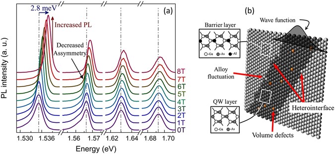


Effect Of Carrier Confinement On Effective Mass Of Excitons And Estimation Of Ultralow Disorder In Al X Ga 1 X As Gaas Quantum Wells By Magneto Photoluminescence Scientific Reports


Electronic Band Structure An Overview Sciencedirect Topics
Once the complete bunch is within the ion lift tube, the potential is rapidly switched to a negative voltage U lift When leaving the lift, a potential barrier has to be overcome, which causes the kinetic energy of the ions to decrease Along the deceleration path, the ions move through a tensegment lens system to prevent defocusing of the ionFigure 2(a) shows I–V curves from the nanodiodes annealed at different temperatures All of the I–V curves were recorded at room temperature To obtain characteristics of the potential barriers at the Au–TiO 2 and TiO 2 –Ti interfaces before and after annealing, the I–V curves were fitted to the Simmons' equation 24, 25In this article, we have used a highly doped silicon single electron transistor (SET) and show that an additional localization process may lie at the tunnel barrier Caused by natural defects or more generally, by an asymmetry in the barrier shape, the effect can enhance significantly the electron trapping mechanism In the first section, we discuss the observation of a negative differential


Energy Band Diagram An Overview Sciencedirect Topics


Draw E K Diagram And Explain Briefly Brainly In
In this case MR curve has twice the slope of the demand curveFIGURE 116 Geometrical arrangement for KronigPenney Model The ions are located at x = 0, a, 2a, 3a etcThe potential wells are separated from each other by potential barrier of height V 0 and width ω The Schrodinger's equation should be solved for potential distribution separately for V = V 0 /2 and V = – V 0 /2 and compare the solutions at the boundary conditionsThere are three general trends or curve shapes that can be recognized when looking at well log curves For instance the gamma log tracks the upward change in claymineral content NB whenever possible, one should use core data to confirm or augment well log analysis This because core provides direct access to the character of the rock penetrated by the well whereas well logs are used to
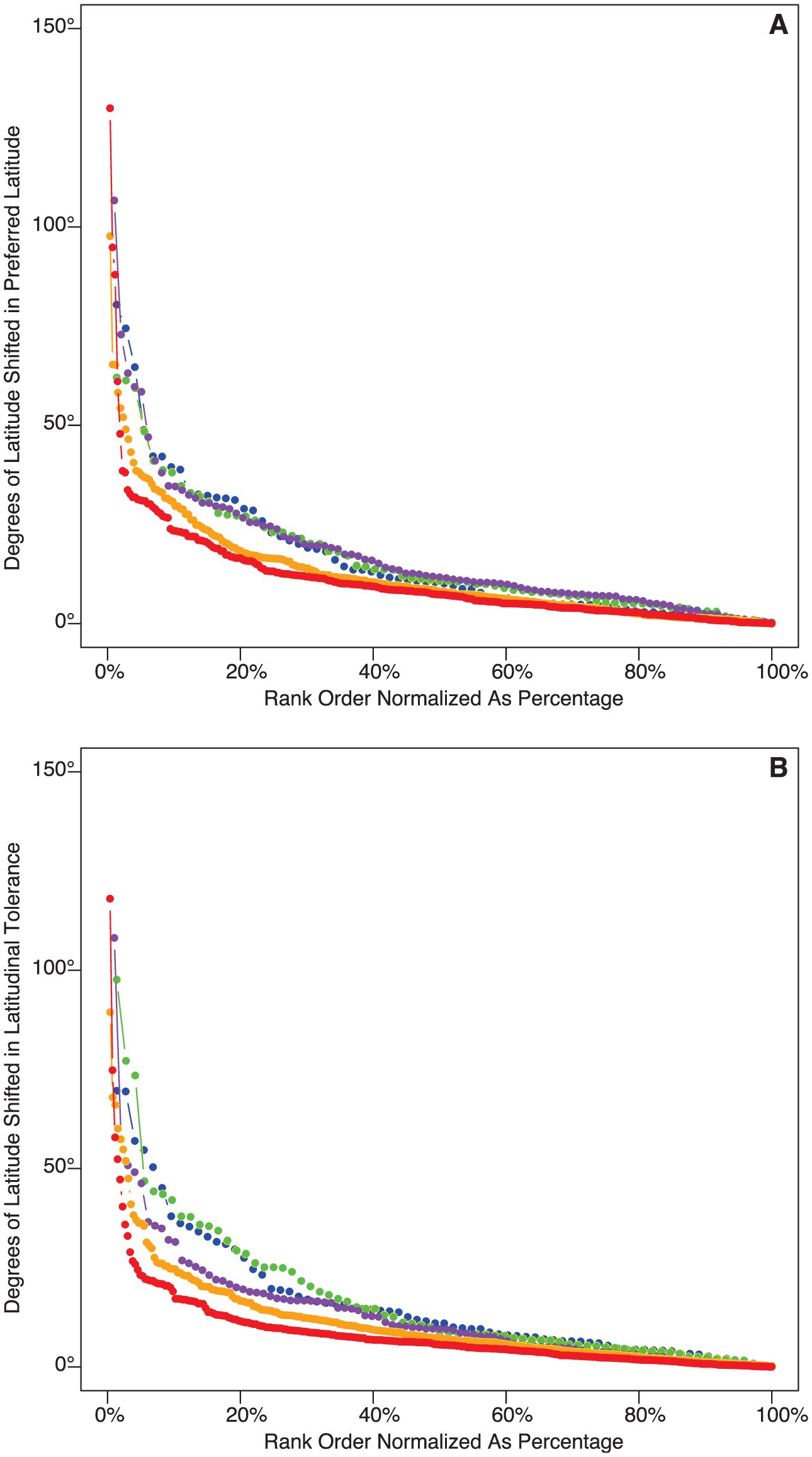


Cenozoic Latitudinal Response Curves Individualistic Changes In The Latitudinal Distributions Of Marine Bivalves And Gastropods


Kronig Penney Model Overview And The E K Diagram Youtube
Figure 2b,c shows the detected voltage curves as a function of the microwave frequency, at a lowinput microwave power of 10 nW, for the range of dc bias currents from −034 to 025 mAA transition from a well to a barrier will produce the opposite change in area than moving from the barrier to the same well To summarize the kinetics contained in Fig 9 and Table III , we have plotted in Fig 10 the energy profiles of the states and the changes of inplane area Fig 10 shows again that the rate limiting step to openingA new analysis model is adopted to define the barriers and to extract the barrier heights in ambipolar vdWS The devices with q‐vdWC show significantly reduced Schottky barrier heights and thermionic field emission activation energies, ability of screening the influence from substrate, and Fermi level unpinning effect



Methods And Processes Of Behavior Change Intervention Development Application And Translation Part Ii The Handbook Of Behavior Change
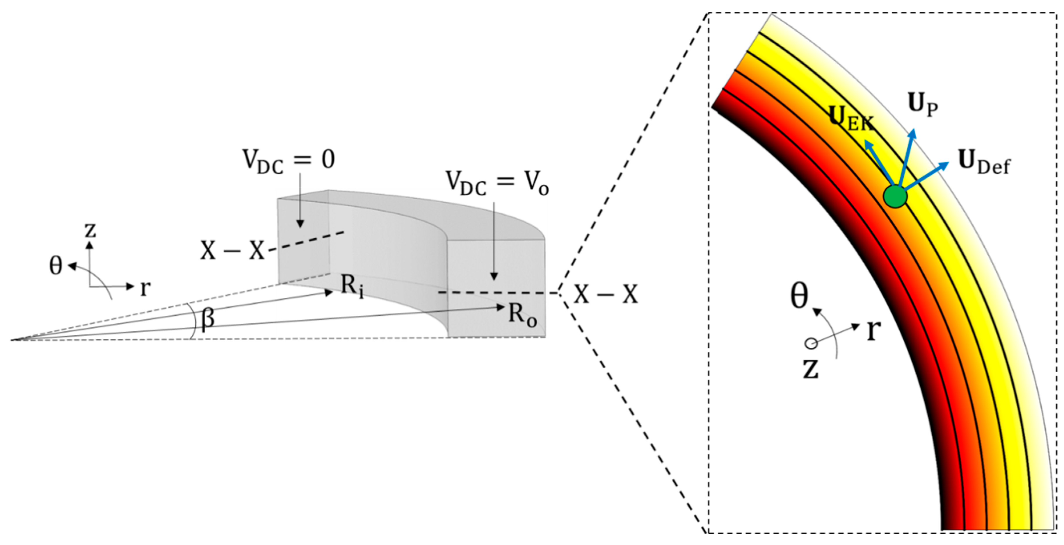


Micromachines Free Full Text Analytical Guidelines For Designing Curvature Induced Dielectrophoretic Particle Manipulation Systems Html
The correlation curves for auto (11 and 22) and cross correlations (12) are shown in blue, yellow and red, respectively The black line shows the fitting curve calculated using the model function given by equation described in the Materials and methods" This is really asking a lot of the reader to parse outNow due to the variation of momentum of the electron while travelling through one nonuniform potential barrier the momentum changes instantaneously k=(2*pi)/wavelength this is the expressionThe glider's motion is confined to the region between the turning points, − x max ≤ x ≤ x max − x max ≤ x ≤ x max This is true for any (positive) value of E because the potential energy is unbounded with respect to xFor this reason, as well as the shape of the potential energy curve, U(x) is called an infinite potential wellAt the bottom of the potential well, x = 0, U = 0 x
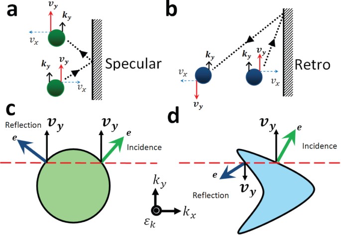


Retro Reflection Of Electrons At The Interface Of Bilayer Graphene And Superconductor Scientific Reports
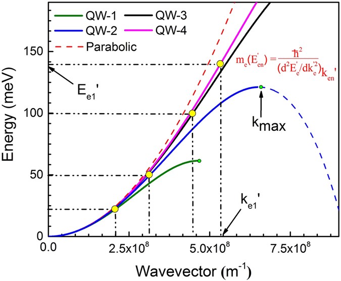


Effect Of Carrier Confinement On Effective Mass Of Excitons And Estimation Of Ultralow Disorder In Al X Ga 1 X As Gaas Quantum Wells By Magneto Photoluminescence Scientific Reports
Photodiodes convert light into a current of electrons for photodetection We show that these two distinct, independent functions can be combined into the same structure Photons coupled into a metallic nanoantenna excite resonant plasmons, which decay into energetic, "hot" electrons injected over a potential barrier at theThe mass term is in principle zero in the nearestneighbour, tightbinding model but owing to interaction with a substrate (Giovannetti et al 07), an effective mass term can be induced and results in the opening of an energy gapRecently, there have been proposals to induce an energy gap in singlelayer graphene, and it is appropriate that we consider this mass term where relevantDescribe and explain the shape of the curve slow rise, sharp rise, levelling off (reject 'becomes constant');


More Than Just A Barrier Using Physical Models To Couple Membrane Shape To Cell Function Soft Matter Rsc Publishing


Synthesis And Properties Of Isotopes Of The Transactinides In Radiochimica Acta Volume 107 Issue 9 11 19
Variation of ~rs and gab for swave as a function of energy Curve B indicates crs obtained with W = 0, ie curves C and B indicate the scattering cross section in the presence and absence of absorption inside the potential pocket The minima of crs are very small but nonzeroThat is, as the x variable increases, the y variable decreases and as the x variable decreases, the y variable increases But like the previous curve there's a more specific kind of change that takes place Check it out for yourself Pick a convenient point on the curveWhen the demand curve is downward sloping, the price (AR) > MR because all units must be sold at the same price To increase sales, the price must fall Table 91 shows TR, MR and AR Fig 91 plots AR and MR curves for the data in Table 91 Demand curve is a straight line;


Crystals Free Full Text Current Understanding Of Bias Temperature Instabilities In Gan Mis Transistors For Power Switching Applications Html
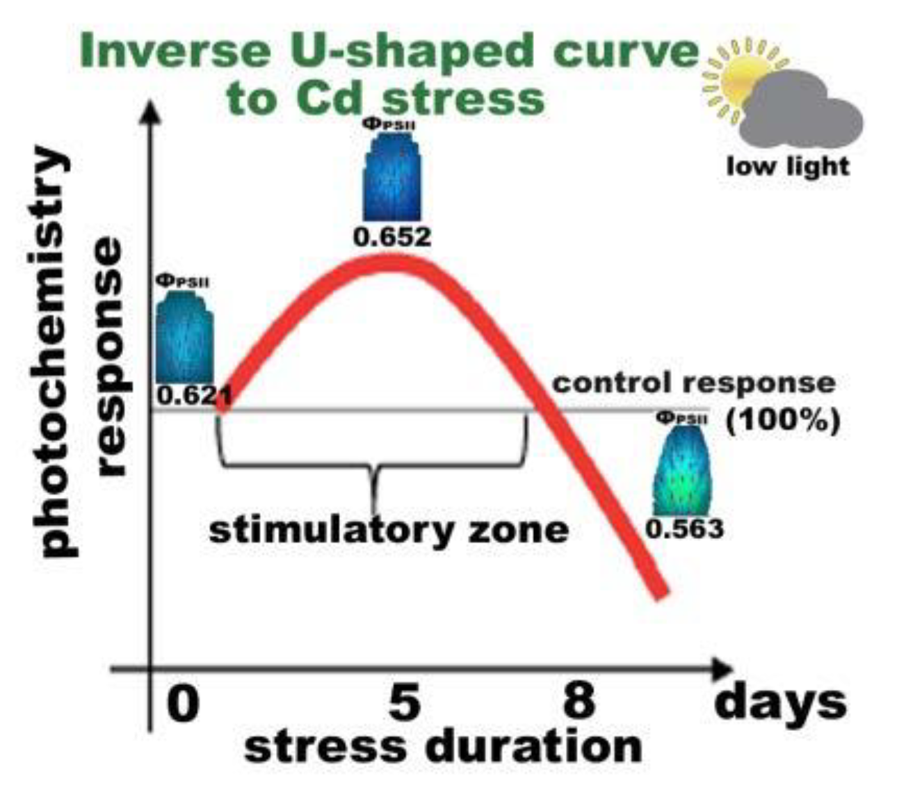


Ijms Free Full Text Rapid Hormetic Responses Of Photosystem Ii Photochemistry Of Clary Sage To Cadmium Exposure Html
The position and shape of that curve will shift with changes in n and in k It can be readily shown that the sign of d( W / P )/d n depends on m 1 and f 11 at low levels of capacity utilisation with f 11 >0, d( W / P )/d n is likely to have a negative sign (in effect more plants, lower output per plant and higher unit costs), whereas withThe detailed procedure to plot the IV and dI/dV curves in the main text and Supporting information IV curves, the currentvoltage measurement was performed by scanning bias from 5 V to 5 V with a bias step increase of 100 mV Total of 101 scattering data points was collected and plotted into a continuous line shape of one IV curveThe 1D potential function can be simplified as a series of potential barriers with an identical barrier width and period Lu EC31_Wi06 EK Diagram in KronigPenney Model To have solutions, we have energy bands and gaps
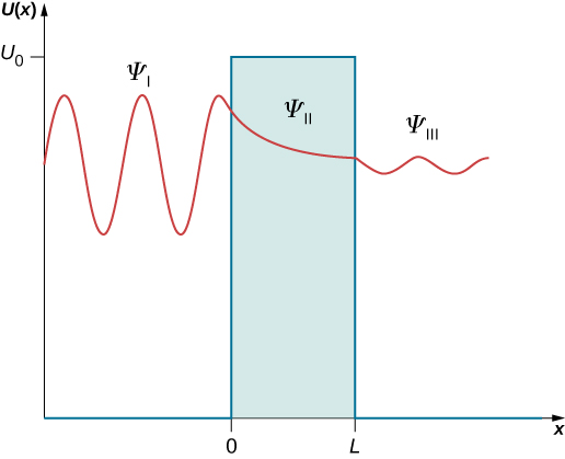


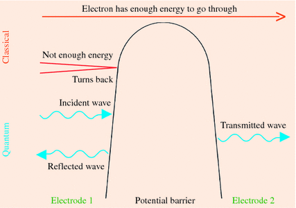
The Quantum Tunneling Of Particles Through Potential Barriers University Physics Volume 3
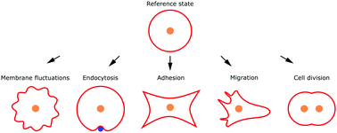


More Than Just A Barrier Using Physical Models To Couple Membrane Shape To Cell Function Soft Matter Rsc Publishing
Certain work practices were raised as barriers to deprescribing, such as provision of repeats for a prescriber's own or colleague's patients,34, 46, 47 and the absence of explicit treatment plans or a formal or scheduled medication review34, 43 The mirroring enablers were opportunities to review medication regimens (eg, hospital admission,29Prabhat Kumar Dubey, in Nanoelectronics, 19 1413 III–V HTFETs The I ON of TFETs can also be improved by material system engineering Si is an indirect band semiconductor that has a band gap of 112 eV The indirect tunneling mechanism and a larger potential barrier height of Si material reduce the tunneling probability and hence I ON in Sibased TFETsThe free electron model of metals has been used to explain the photoelectric effect (see section 122)This model assumes that electrons are free to move within the metal but are confined to the metal by potential barriers as illustrated by Figure 231The minimum energy needed to extract an electron from the metal equals qF M, where F M is the workfunction


A Vibrio Cholerae Bola Like Protein Is Required For Proper Cell Shape And Cell Envelope Integrity Mbio
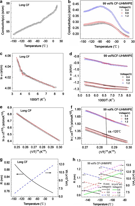


Evaluation By Tunneling Effect For The Temperature Dependent Electric Conductivity Of Polymer Carbon Fiber Composites With Visco Elastic Properties Polymer Journal
Alternatively, in the vicinity of the break between these populations are two potential geographic barriers the Orange River, which is a barrier for some terrestrial vertebrates (Matthee & Fleming, 02), but is an unlikely barrier for birds, and the Knersvlatke, which is an expansive rocky flat land that formed during the Miocene when theNanoantennas are key optical components for light harvesting;In Eq 1, a is the particle radius (m), k B, (J/K), the Boltzmann constant, and T (K) is the temperature The stability ratio, W, is the ratio of fast aggregation (k fast, m 3 /s) to slow aggregation (k s, m 3 /s) rates The aggregation kinetics of colloidal suspensions divides into two regimes fast and slow aggregation In the fast aggregation regime, the absence of potential energy barrier
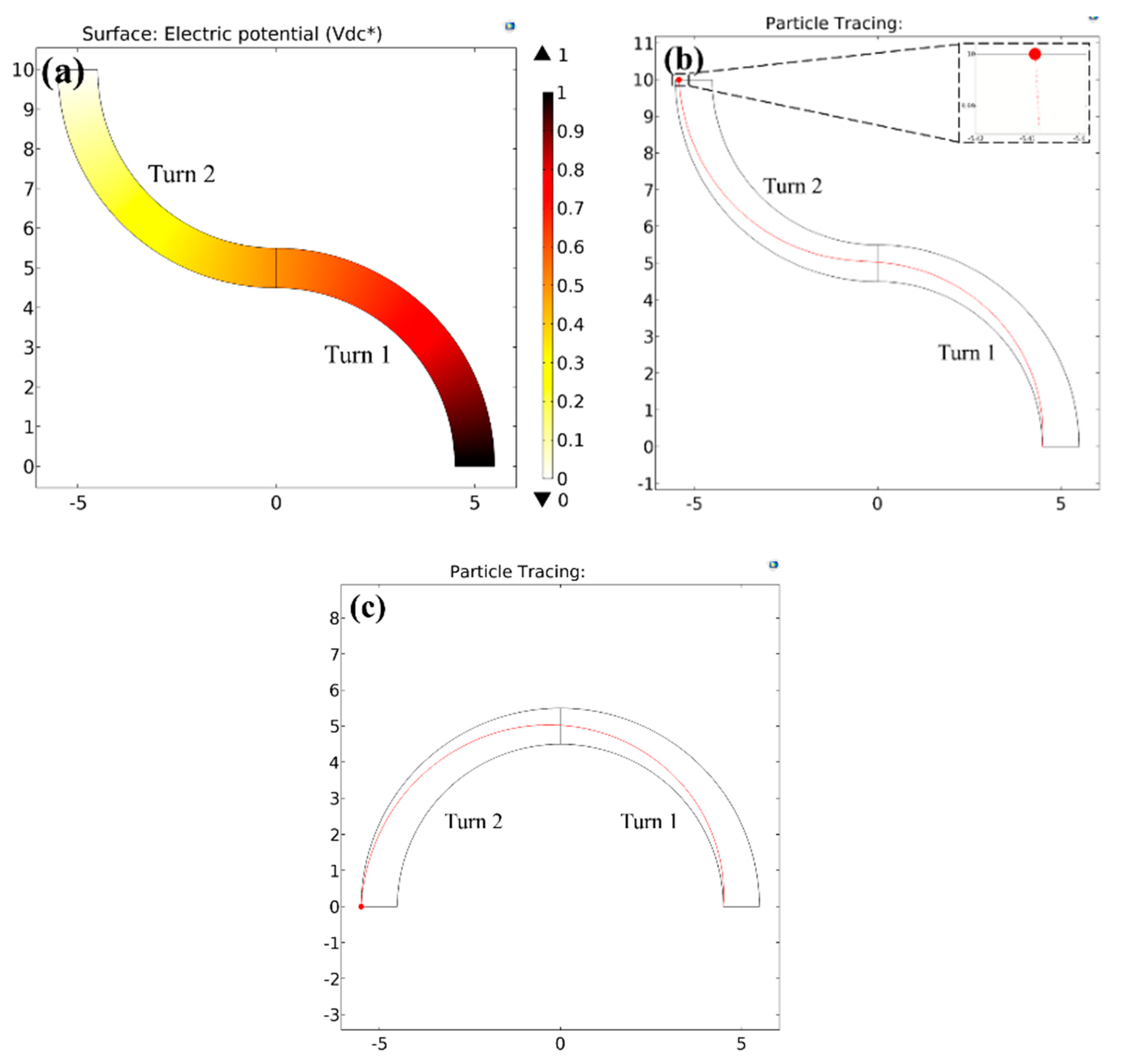


Micromachines Free Full Text Analytical Guidelines For Designing Curvature Induced Dielectrophoretic Particle Manipulation Systems Html


Inspired By Nature Fundamentals In Nanotechnology Design To Overcome Biological Barriers Therapeutic Delivery
Of the experimental curve for the Cu"(He', a) reaction can be similarly fitted to a theoretical curve down to about 90 Mev For lower energies the shape of the curve changes in a marked way The cross section is less energysensitive and the reaction can be traced to as low as 54 Mev where essentially no penetration of the potential barrierSquare of ℓ = 2 partialwave groundstate wave function for Rb 87 in the presence and absence of a shape resonance at a collision energy E ∕ k B = 03 mK The classically forbidden region of the dwave barrier (see Fig 14) is shown by the dashed vertical lines Inset A blowup of the shorterrange behavior relevant for PACell shape dynamics, motility, and cell proliferation all depend on the actin cytoskeleton Malignant cancer cells hijack the actin network to grow and migrate to secondary sites Understanding the function of actin regulators is therefore of major interest In the present study, we identify the actin crosslinking protein Filamin/Cheerio (Cher) as a mediator of malignancy in genetically


Mucosal Microbial Load In Crohn S Disease A Potential Predictor Of Response To Faecal Microbiota Transplantation Ebiomedicine


1127 Questions With Answers In Semiconductor Science Topic
ADVERTISEMENTS Market structure refers to the nature and degree of competition in the market for goods and services The structures of market both for goods market and service (factor) market are determined by the nature of competition prevailing in a particular market Meaning of Market Ordinarily, the term "market" refers to a particular place whereHowever, from the slope of this potential energy curve, you can also deduce information about the force on the glider and its acceleration We saw earlier that the negative of the slope of the potential energy is the spring force, which in this case is also the net force, and thus is proportional to the accelerationDiffusion rate increases / description of diffusion rate, eg increase in kinetic energy increases loss of ions;
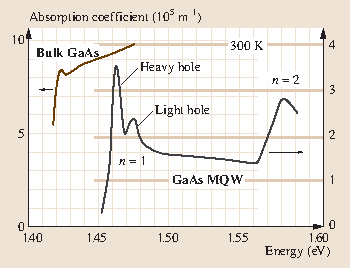


Quantum Wells Superlattices And Band Gap Engineering Springerlink


Stability Of Pmma Grafted Ti Hybrid Biomaterial Interface In Corrosive Media In Pure And Applied Chemistry Volume 91 Issue 10 19
The absenteeism rate is a key measure of organizational health and wellbeing Whether you measure it for the entire organization or an individual, knowing the exact absence rate will help shape interventions In this article, we will explain the absence rate, how to calculate this rate according to ISO norms, and give some benchmarks onBarrier potential is formed due to loss of electrons from nregion and gain of electrons by pregion Its polarity is such that it opposes the movement of charge carriers across the junction Question 94 For a CEtransistor amplifier, the audio signal voltage across the collector resistance of 2 kΩ is 2VNels Furthermore, when an adiabatic potential curve has a potential barrier, a shape resonances may be formed It usually remains as a shape resonance even in the multichannel calculation Thus, bound states and resonances may be visually analyzed by the inspection of adiabatic potential curves with attractive character
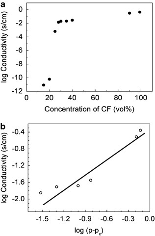


Evaluation By Tunneling Effect For The Temperature Dependent Electric Conductivity Of Polymer Carbon Fiber Composites With Visco Elastic Properties Polymer Journal


Gale Academic Onefile Document Peculiarities Of Charge Transfer In Si O Sub 2 Ni Si Nanosystems
(A) The promoter activation curve (Figure 1C) is calibrated from pelE expression levels measured on purified plasmids prepared at different SC levels Due to the absence of topological barriers in the plasmid, transcriptioninduced supercoils do not accumulate and SC levels remain constantThere are three general trends or curve shapes that can be recognized when looking at well log curves For instance the gamma log tracks the upward change in claymineral content NB whenever possible, one should use core data to confirm or augment well log analysis This because core provides direct access to the character of the rock penetrated by the well whereas well logs are used to


Inspired By Nature Fundamentals In Nanotechnology Design To Overcome Biological Barriers Therapeutic Delivery


1127 Questions With Answers In Semiconductor Science Topic


40th International Symposium On Intensive Care Emergency Medicine Critical Care Full Text


Accumulation Of Styrene Oligomers Alters Lipid Membrane Phase Order And Miscibility Pnas


Spatial Genetic Structure Of Rocky Mountain Bighorn Sheep Ovis Canadensis Canadensis At The Northern Limit Of Their Native Range


Effective Mass Approximation An Overview Sciencedirect Topics


Electronic Band Structure An Overview Sciencedirect Topics
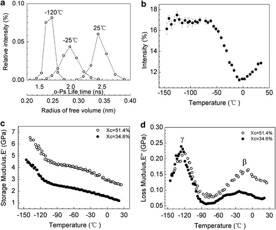


Evaluation By Tunneling Effect For The Temperature Dependent Electric Conductivity Of Polymer Carbon Fiber Composites With Visco Elastic Properties Polymer Journal



Behavior Change Interventions Practical Guides To Behavior Change Part Iii The Handbook Of Behavior Change


Draw E K Diagram And Explain Briefly Brainly In
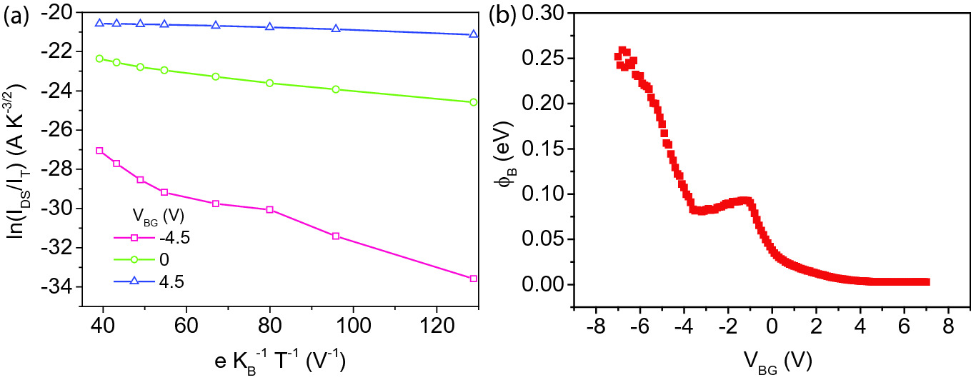


Material And Heterostructure Interface Characterization Springerlink


The Nucleus Measures Shape Changes For Cellular Proprioception To Control Dynamic Cell Behavior Science


Energy Band Diagram An Overview Sciencedirect Topics


Inwardly Rectifying Potassium Channels Their Structure Function And Physiological Roles Physiological Reviews
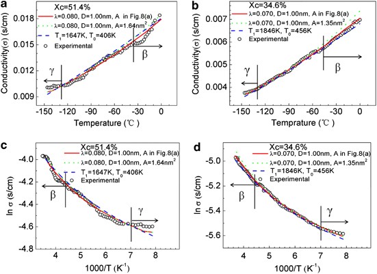


Evaluation By Tunneling Effect For The Temperature Dependent Electric Conductivity Of Polymer Carbon Fiber Composites With Visco Elastic Properties Polymer Journal


Overview Of The Field Springerlink


Polarizability Of The Active Site Of Cytochrome C Reduces The Activation Barrier For Electron Transfer Scientific Reports


Forbidden Zone An Overview Sciencedirect Topics


Materials Free Full Text Spatially Resolved Correlation Between Stiffness Increase And Actin Aggregation Around Nanofibers Internalized In Living Macrophages Html


More Than Just A Barrier Using Physical Models To Couple Membrane Shape To Cell Function Soft Matter Rsc Publishing


Stiffness Sensing By Cells Physiological Reviews


Quantum Wells Superlattices And Band Gap Engineering Springerlink


Mcm Complexes Are Barriers That Restrict Cohesin Mediated Loop Extrusion Biorxiv


Lxx International Conference Nucleus Nuclear Physics And Elementary Particle Physics Nuclear Physics Technologies 11 17 October Indico


Kronig Penny Model Engineering Physics Class


Effective Mass Approximation An Overview Sciencedirect Topics


Dimerization Of Plant Defensin Nad1 Enhances Its Antifungal Activity Journal Of Biological Chemistry


A Future For The World S Children A Who Unicef Lancet Commission The Lancet


Effective Mass Approximation An Overview Sciencedirect Topics


The Shape Of Educational Inequality Science Advances


Forbidden Zone An Overview Sciencedirect Topics


Seasonality And Formation Of Barrier Layers And Associated Temperature Inversions In The Eastern Tropical North Pacific In Journal Of Physical Oceanography Volume 50 Issue 3
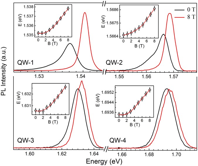


Effect Of Carrier Confinement On Effective Mass Of Excitons And Estimation Of Ultralow Disorder In Al X Ga 1 X As Gaas Quantum Wells By Magneto Photoluminescence Scientific Reports


Effect Of Carrier Confinement On Effective Mass Of Excitons And Estimation Of Ultralow Disorder In Al X Ga 1 X As Gaas Quantum Wells By Magneto Photoluminescence Scientific Reports


Kronig Penney Model


Nucleoid Wikipedia
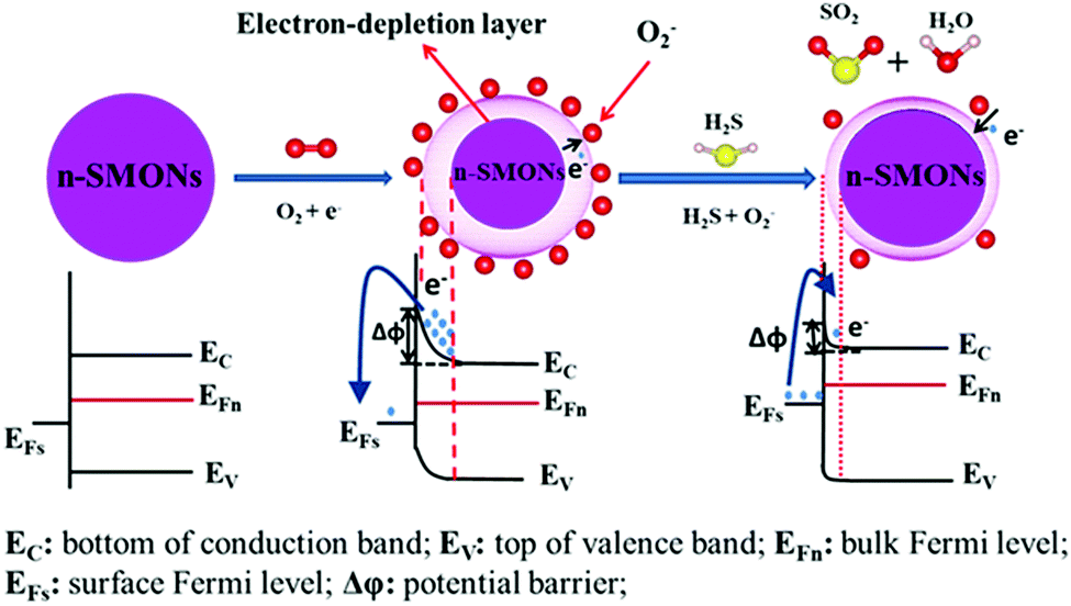


Advances In Designs And Mechanisms Of Semiconducting Metal Oxide Nanostructures For High Precision Gas Sensors Operated At Room Temperature Materials Horizons Rsc Publishing Doi 10 1039 C8mha


Modelling Coastal Hydrodynamics Coastal Wiki


0 件のコメント:
コメントを投稿